
MST MECHANICAL ASSEMBLY AI · CONTROLLED PILOTS OPEN
Turn P&ID and your PDM models into a native SolidWorks assembly.
MST Mechanical Assembly AI is an implemented, controlled-scope capability. It understands P&ID process intent, resolves approved native models from the customer’s authorized PDM scope, directs SolidWorks to build a native editable assembly and reads the result back for engineering review.

P&ID → OPTIMIZED PHYSICAL ARRANGEMENT
A P&ID defines what connects. MST solves where every approved component should go.
Within a declared engineering boundary, two coupled solvers search for a compact, feasible physical result. A layout change reshapes the routes; an infeasible route sends the layout back for another candidate.
Optimization boundary: “Optimized” means selected against the customer-approved objectives, hard constraints, search space and stopping criteria. It is not a claim of a universal global optimum, and engineers retain release authority. Read the P&ID-to-assembly answer
01 / THE BRAIN
Understand. Model. Plan. Orchestrate. Verify.
MST first understands P&ID equipment, pipelines, interfaces, flow and connection intent—then turns that context into an inspectable physical result.
Explore the intelligence loopINTENT
- 01UNDERSTAND
- 02MODEL
- 03PLAN
- 04ORCHESTRATE
- 05VERIFY
ASSEMBLY

02 / THE TOOL RELATIONSHIP
MST decides. Engineering systems execute.
In the controlled workflow, MST resolves approved native SolidWorks part models from the customer’s PDM, directs SolidWorks to generate the assembly and reads it back for verification.
Configured when required: CAD · CAE · PDM/PLM · ERP
See the tool architecture03 / IMPLEMENTED MECHANICAL ASSEMBLY AI
From P&ID intent and approved customer PDM models to a native, editable SolidWorks assembly.
MST has implemented this controlled workflow using customer-approved native part models—not regenerated substitutes—with reopen/read-back verification and PASS, FAIL or CANNOT_VERIFY outcomes under engineer release authority.
Public run proof is held to the same standard: a single run identity must bind the input, plan, native assembly, reopen/read-back facts, deterministic verdict and engineer review.
Review the verification method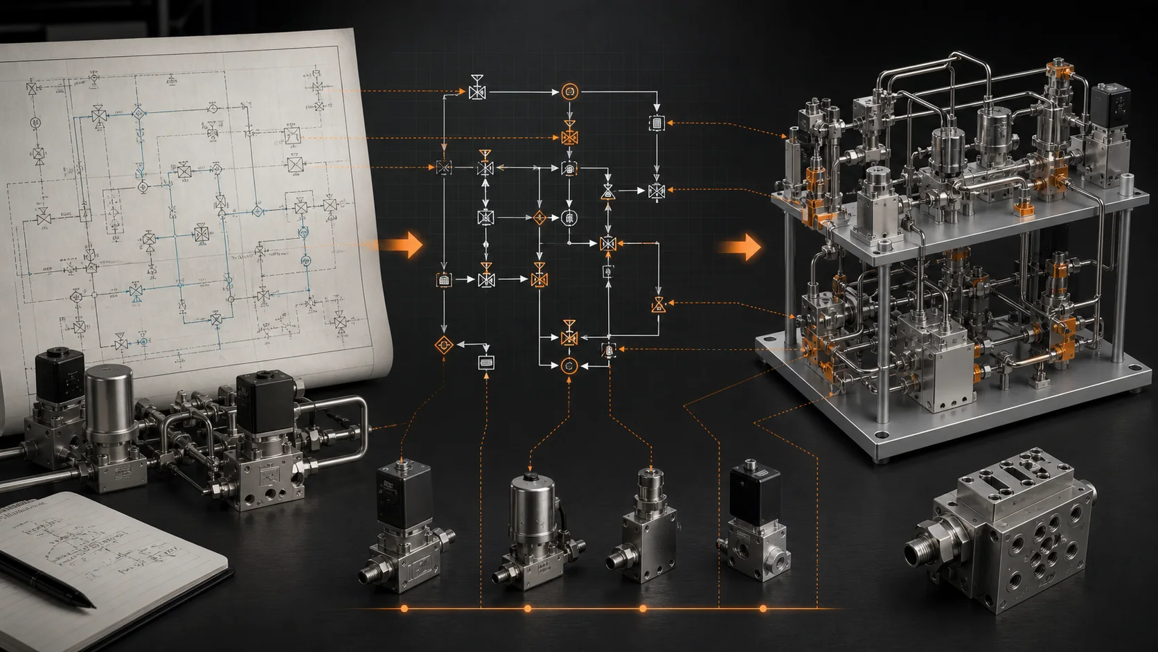

05 / PROVE IT
Bring one real engineering case.
See what MST understands, which approved PDM parts it resolves, how it uses SolidWorks, what it verifies and where it stops.
Request a live challenge